Deep Sounds – Tests at Wheatley
july 2012

Digging down a meter
I want to make an installation with the experience of a live sound wave or pressure wave from deep in the earth. I’m keen to set this exotic sound in a garden of an ordinary house in a city to emphasise the ongoing nature of the planet even while we are just living our daily lives – watching the Olympics, cooking the supper etc……!
My question is – how low can I go?
I asked Bristol University Geology Department whether it would be better to try listening under Bristol or under Oxford. The answer was that if I didn’t want to make accurate scientific calculations I could go to either place, but Bristol was built on more rock than Oxford.
“The quality of the data from a seismic sensor is strongly affected by local conditions at a site. For best seismic fidelity, seek a site with shallow soil cover over bedrock and away from roads or human activity. Site conditions in Bristol are slightly better than Oxford due to the deeper soil and sediment layers in Oxfordshire, but there is more human-generated noise. (Wiltshire’s chalk deposits are quite poor seismic sites.) There is always a compromise involved in selecting a site.”
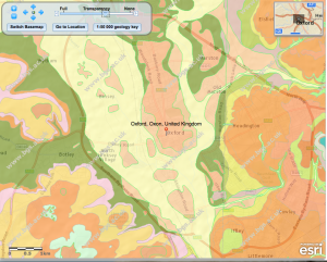
Image of under ground geology of Oxford
http://mapapps.bgs.ac.uk/geologyofbritain/home.html
(See website for key to rock formations shown)
I want to find out what equipment I can use for this installation to pick up low frequencies from a geophone or geophones and play it through either a PA system into a speaker cone, or via a transducer into the walls of the house or object like a wardrobe to feel the vibrations.
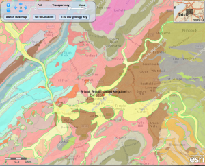
Image of under ground geology of Bristol
http://mapapps.bgs.ac.uk/geologyofbritain/home.html
In terms of how to present the installation I want to convey to the visitor:
• The experience of the intermittent live sound wave vibrations either audible or inaudible – (showing they are very long waves)
• The distance through the ground the sound has travelled – (large sized waves travel a great distance through the earth)
I wonder if a listener’s experience of a VIBRATION from a very large sound/pressure wave would need more explanation than a very low just audible SOUND from a pressure/sound wave?
Here is a description of some tests I made to help the process of making the installation.
While some Oxford Brookes University sound equipment was being calibrated at the Wheatley campus, I was able to set up outside with different combinations of geophones to see how they behaved with the University’s PA system. (1000W amp and several PS2 12” speaker cones having a lower range down to 25Hz)
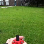
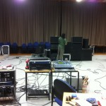
Red geophone being placed in the ground connected to the equipment inside the hall
I set out to find out 3 things:
1. QUESTION should I use the Wheatley sound equipment with the geophone/s I have?
2. QUESTION should I use a phased array of geophones to make a stronger signal?
3. QUESTION should I place the geophones at an angle down into the ground for deeper frequency sounds?
ANSWER 1.
The equipment sounded good amplifying the geophone. It also felt interesting to feel the vibrations. The equipment however was built to deal with audible sounds over 25Hz and 29Hz, so were we experiencing any frequencies lower than 25Hz?
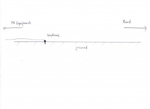
Above -one geophone picking up underground sounds from the road
ANSWER 2.
I learnt about the time delay to make a stronger signal with a phased array. The phased array with the geophones lined up towards the sound source (the road approximately 60m away) did sound stronger. We tried two phased arrays on the surface of the ground (not dug down). The line with greater distance between the geophones had a more contrasting and stronger sound than the geophones with less distance between them.

Above – phased array of geophones on the surface of the ground a) 1 m and b) 12 m apart
phased array 12 m gap
(listen with head phones)
Information about Time Delay:
To match up the sounding time of all three geophones, so they all would be heard at the same time (maximising the strength of the signal) the sound from the two geophones at shorter distances from the desk had to be delayed. A time delay is when the desk is programmed to delay the sounding of a signal.
Calculating the time the sound took to travel between the geophones informed us of what lengths of time the delays should be ( to round figures). We calculated that:
• If the distance between one geophone and the next were 3.70 meters, the sound took .5 of a millisecond to travel through the ground between them.
• If the distance was 1meter sound took .2 of a millisecond to travel between them.
• If the distance was 1.90 meters, the sound took .3 of a millisecond.
ANSWER 3.
Listening to the recordings of the phased arrays with and without the angle or downward tilting slope, a slight difference could be heard by ear. We created two different angles to the ground surface. One was steeper than the other. I could not tell by ear if the sounds were lower with the more steeply sloped downward angle, although they sounded different.
Here is best phased array

Above a phased array of geophones on an angle to the grounds’ surface


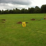
Line of geophones on the flat ground surface, angled downwards
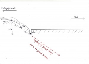
Above a phased array of geophones in a steepler angle to the grounds surface
[audio:https://shirleypegna.com/wp-content/uploads/2012/08/phased-array-angled-down5.mp3|titles=phased array angled down]
Listening to the sound of phased array with the geophones at a steeper angle
(use headphones for listening)
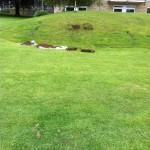


Geophones dug into small slope
Our tests were more exploratory than scientifically planned out, and rather than getting definitive answers I was able to experience the equipment working and understand how to ask different questions for setting up the installation:
1. I found it was possible to cut off the higher frequencies that were coming from the ground (at the desk) above 35 Hz, and listen to the audible contrasting signals of the lower register. (The desk could not cut off lower frequencies than 35Hz if we wanted to isolate lower frequencies).
2. I found that to verify that the frequencies from the two downward facing phased arrays were different from the arrays on the grounds’ surface, it would require an instrument like an oscilloscope or spectrograph – which I didn’t have at that time. Is it possible to get a spectrograph that registers frequencies of 2Hz-7Hz- 10Hz?
3. I found that when we sent a sine wave (an isolated wave) through the sound system, you could feel the speaker vibrate. There fore the system could convey very low frequencies at a low db level – contrary to what it said on the equipment spec.(which specified 25Hz as its lowest rang). So (for my installation experiencing vibration and the lowest audible sound) would I need a speaker larger than 21” to convey lower vibrating frequencies?
4. I found that it wouldn’t be easy to isolate, experience and identify the LOWEST live sound wave/vibration in a live ground sound signal with a mixture of frequencies. Is there perhaps a desk or software that would cut off all frequencies over10Hz or lower? High and Low pass filters exist for seismic instruments, but do they exist for audio instruments that low?
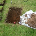
Thanks to the Brookes groundsmen for coming to my aid, looking like Time Team, and helping dig and provide me with some history of the ground itself. Digging down under the well kept grass ‘dug up’ memories of the cables being laid for the then new University buildings and one groundsman remembered playing here as a boy, where there once stood a WW2 hospital – the wounded came here to be ‘out of sight’.
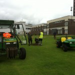


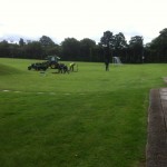
Wheatley Campus ‘ Time Team’
Thanks also very much to David Carugo, John Glasgow and Danny Bhatt for their time, expertise – technical and mathematical – and lots of helpful ideas.
End